Capillary channel flows (CCF)
The mechanics of open capillary channel flow has been a research topic in the Fluid Mechanics and Multiphase Flows group since the mid-nineties. The motivation for this research is to improve existing space applications and to develop new models required for the efficient liquid management in space. Proper understanding of the liquid behaviour in the microgravity plays a key role in designing systems such as propellant management devices or life support systems (waste water management or heating exchange systems). Due to the existence of the gravitational force on Earth researchers need to simulate microgravity conditions needed for their experiments by using drop towers or perform their experiments in space.
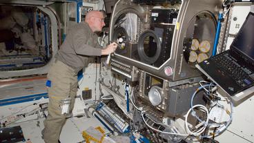
Previous studies of open capillary channel flows in drop tower experiments and sounding rocket flights have shown that free surfaces destabilise and gas ingestion occurs when a critical flow rate is exceeded. This phenomenon is called ‘choking’ and can lead to technical disadvantages or even system failures. To examine this phenomenon and capillary channel flow stability in general, researchers decided to install their experimental unit on-board the International Space Station.
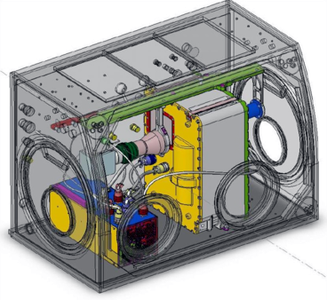
The Capillary Channel Flow (CCF) experiment was launched to the ISS on-board the Space Shuttle Discovery (STS-131) on April 5th, 2010. The hardware was initially installed into the Microgravity Science Glovebox (MSG) in December 2010. The experiment units are designed to be controlled from ground stations in Bremen and Portland (USA). The experiment setup is modular and consists of one of the two experiment units (EU), both containing an entire fluid loop with test channel, the electrical subsystem (ESS) consisting of the power supply and control units, and the optical diagnostic unit (ODU), which consists of a high speed camera and a parallel light source. Due to the modular setup, the experiment unit can be exchanged to investigate different flow channels. Experiments were performed with EU1 throughout the first quarter of 2011 after which CCF was placed back into stowage. EU2 was installed in mid-September 2011 and was operational until mid-October 2011.
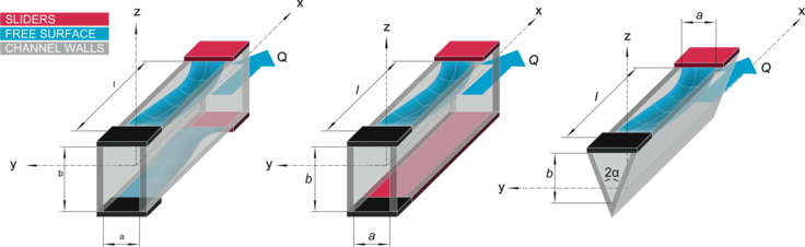
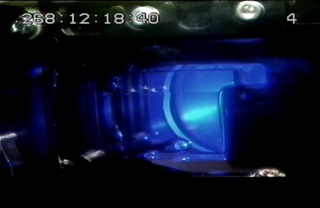
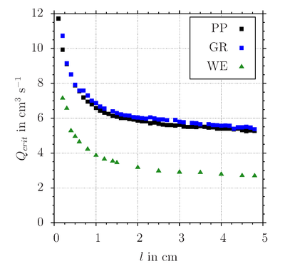
The test liquid (NovecTM Engineered Fluid HFE-7500) is pumped through an open capillary channel. During the experiment the flow rate is increased until the gas-liquid interface collapses and gas ingestion occurs. Three channel geometries were used in the experiments: parallel-plates, a groove, and a triangular wedge. Slide bars were used to vary the length of the interface. The test channels are made of glass so that the dynamics of the interface may be recorded by a high speed camera.
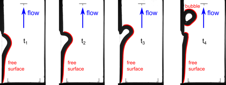
High speed images were recorded to investigate the behaviour of the free surface. In reduced gravity the pressure difference between the liquid in the channel and the ambient gas is balanced by the curvature of the interface. As pressure decreases in flow direction the curvature increases to balance the rising pressure difference. If the curvature of the free surface is no longer sufficient to balance the pressure difference, the interface collapses ingesting gas into the channel. This occurs in steady flow when the flow rate exceeds a critical value Qcrit.
Critical flow rates were determined for steady, laminar flow in each of the channels for various interface lengths. Results show that the critical flow rate decreases with increasing channel length l.
[1]Canfield et al.: The capillary channel flow experiments on the international space station - experiment setup and first results, Experiments in Fluids (2013, submitted).
[2]Grah, A., Dreyer, M. E.: Dynamic stability analysis for capillary channel flow: One-dimensional and three-dimensional computations and the equivalent steady state technique, Phys. Fluids 22, 014101 (2010).
[3]Haake, D., Klatte, J., Grah, A., Dreyer, M. E.: Flow rate limitation of steady convective dominated open capillary channel flows through a groove, Microgravity Sci. Tec. 22, 129-138 (2010).
[4]Rosendahl, U., Grah, A. and Dreyer, M. E.: Convective dominated flows in open capillary channels, Phys. Fluids 22 (052102), (2010).
[5]Grah, A., Haake, D., Rosendahl, U., Klatte, J., Dreyer, M. E.: Stability limits of unsteady open capillary channel flow, J. Fluid Mech. 600, 271-289 (2008).
[6]Klatte, J., Haake, D., Weislogel, M. M., Dreyer, M. E.: A Fast Numerical Procedure for Steady Capillary Flow in Open Channels, Acta Mech. 201 (1-4), 269-276 (2008).
[7]Rosendahl, U., Dreyer, M. E.: Design and performance of an experiment for the investigation of open capillary channel flows, Exp. Fluids 42 (5), 683-696 (2007).
[8]Haake, D., Rosendahl, U., Ohlhoff, A., Dreyer, M. E.: Flow Rate Limitation in Open Capillary Channel Flows, Ann. NY Acad. Sci. 1077, 443-458 (2006).
[9]Rosendahl et al.: Choked flows in open capillary channels: theory, experiment and computations. J. Fluid Mech. 518 (2004), 187–214.
[10]Rosendahl, U., Ohlhoff, A., Dreyer, M. E., Rath, H. J.: Investigation of Forced Liquid Flows in Open Capillary Channels, Microgravity Sci. Tec. 13 (4), 53-69 (2002).
[11]Dreyer et al.: Experimental investigation on flow rate limitations in open capillary flow. In 34th AIAA/ASME/SAE/ASEE Joint Propulsion Conference (1998), no. AIAA 98-3165.
