hot windtunnel
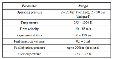
The hot windtunnel (HWK) serves for investigations on fuel spray autoignition in a hot gas flow. The gas can be air or all mixtures that are stable und high temperature conditions. The fuel can be any hydrocarbon fuel that can be dispersed via an injection nozzle. The main purpose of the facility is to investigate spray autoignition under as-real conditions as can be seen from the specification table below. The HWK´s injection section can be designed as a real burner with jet-in-crossflow injection or else. The gas flow velocity depends on the pressure of the charging pressure as well as on the diameter of the exhaust nozzle. The flow´s turbulence can be adjusted through appropriate turbulence generators.
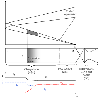
The HWK functions as a Ludwieg – tube, where the steady flow is established in-between a transient wave system and only remains steady for a limited amount of time (depending on the length of the charge tube), in this case 100ms (Figure 2).
In contrast to normal Ludwieg – tubes however, the flow in the driver section is used for the experiments, while ordinarily the high mach-number flow after the nozzle in the driven section is used for experiments.
The flow in the driver section exhibits high temperature and high pressure with slow to moderate flow velocities. These conditions are similar to those found in many combustion machines (aircraft or power generation turbines for example). The experimental time available is dependent of the length of the driver section, as the conditions behind the established waves are constant until the return of the reflected wave from the closed end.
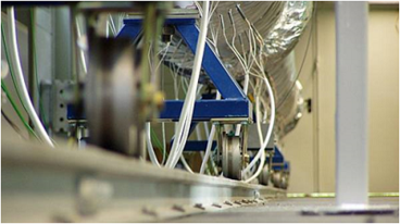
Main components of the facility can be seen in Figure 1. The driver section is closed against the surroundings through a fast acting main valve just upstream of the nozzle. The main valve is actuated pneumatically and is fed through the main pressurisation system. The next component upstream is the three meter long test section of the wind tunnel with several observational ports. The fuel injection system is located at the last upstream window of the test section in order to allow sufficient time for the spray to disperse and ignite after injection. The entire test section and fuel injection system are cooled through a water cooling system. This serves two purposes, the first one being mechanical (i.e. preventing distortions of the test section through temperature gradients), while the second reason is to prevent any wall impinging spray to ignite and in doing so falsify the experimental results.
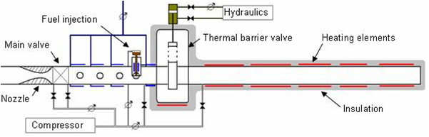
In addition to this the large diameter of the test section of 336mm also serves to keep the spray separate from the walls and allows the installation of large test bodies to influence the flow in any desired way.
The test section and the main part of the driver section are separated through a thermal barrier valve. This valve is not airtight but it prevents the heated air from the remainder of the driver section to seep into the test section prior to the experiment. This also serves the purpose of keeping the walls of the test section at room temperature throughout an experimental campaign. The thermal barrier valve (TBV) is opened just prior to the opening of the main valve and start of the experiment via a hydraulics system. This system allows very fast opening times of the TBV (less than 0.5s) in order to minimize convection effects (and resulting degradation of the thermal profile) once the hot an cold sections of the HWK are connected.
The last main component upstream of the thermal barrier valve is the 40 m long heated driver section, which is (as well as the thermal barrier valve) thermally insulated, to prevent heat loss and encourage an even temperature distribution. This section can be electrically heated up to a temperature of 1000K.
The overall objectives of this facility are to help in the investigation of:
- Efficient combustion of liquid fuel sprays and therefore the development of optimized combustion techniques for fuel reduction in technical applications
- Reduction of pollutant emissions, especially NOx
- Validation of numerical simulation for spray autoignition
- Development and implementation of modern (optical) measurement techniques
