groove channel
critical velocities in an open capillary groove
Introduction
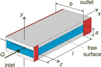
As an example for a capillary channel a groove is shown in Figure 1. The liquid flows along the x-axis from the inlet to the outlet and forms a free surface at the open side between the plates. The flow is maintained by external pumps and the free surface deforms corresponding to the pressure along the flow path.
Due to convective and viscous momentum transport the pressure along the flow path decreases and causes the free surface to bend inwards. The maximum flow rate is achieved when the free surface collapses and gas ingestion occurs at the outlet. This critical flow rate depends on the geometry of the channel and the properties of the liquid.
experimental setup
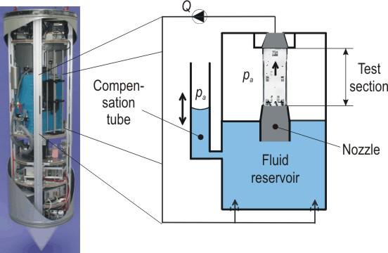
The experiment was developed to operate within a drop capsule (left side of Figure 2) of the Bremen drop tower. With the 110 m long drop tube evacuated to approximately 10 Pa the drop tower provides a free fall of 4.74 s with a residual acceleration less than 10-5 g.
The experimental setup consists of a fluid reservoir filled with test liquid and the groove which is fixed upright on the reservoir. A pump enables a closed fluid circuit. The pump withdraws the liquid at the outlet of the test section and feeds it into the fluid reservoir. Before entering the test section, the flow is accelerated and rectified by a nozzle. Differences in volume after gas ingestions are compensated by the compensation tube. Figure 2 shows a schematic drawing of the experimental setup. Two CCD cameras could be used for flow observation and to determine the shape of the free surface.
results
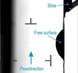
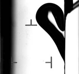
On the pictures below you can see an example of a sub- and a supercritical flow through the groove, thereby the camera view is in the negativ y-direction. Because of total reflectance of light on the free surface the free surface could be seen as black shadow on the right side of the groove (see also figure 3a).
Figure 3a shows the subcritical flow at which the free surface bend inward and reaches steady state. In figure 3b you can see the supercritical flow, where gas ingestion occurs at the outlet.
The funding of the drop tower flights and the funding of the research project by the German Federal Ministry of Education and Research (BMBF) through the German Aerospace Center (DLR) under grant number 50WM0241 are gratefully acknowledged.
publication
- Haake, D., Rosendahl, U., Ohlhoff, A., Dreyer, M.E.: "Critical Velocities and Flow Rate Limitation in Open Capillary Channel Flows (CCF)", Talk of the 76th GAMM-Conference, 28.3.-1.4.2005, Luxembourg
- Haake, D., Ohlhoff, A., Dreyer, M.E., Rath, H.J.: "Critical Velocities in Open Capillary ChannelFlows (CCF): Groove", Talk of the 7th Drop Tower Days, Sept. 12-15, 2004, Bremen, Germany
- Haake, D., Rosendahl, U., Ohlhoff, A., Dreyer, M. E.:"Flow Rate Limitation in Open Capillary Channel Flows (CCF)", Interdiciplinary Transport Phenomena in Microgravity and Space Sciences IV, 7-12 August 2005, Tomar, Portugal.
