CCF on TEXUS-42
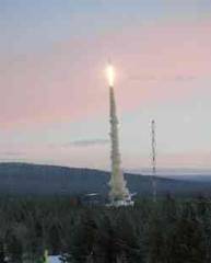
The CCF (Capillary Channel Flow) Experiment has been launched with the sounding rocket TEXUS EML-1 on December 1, 2005 from Esrange, North Sweden. During the 6 min and 37 sec of microgravity time the CCF crew performed several experiment procedures via telecommand. The experiment yields new results about forced flows in capillary channels.
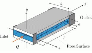
The capillary channel consists of two parallel plates of breadth b = 25 mm and distance a = 10 mm. The length of the channel is adjustable between l = 12 mm and l = 19 mm. A flow through the channel is maintained by a gear pump connected to the outlet. Liquid is provided by a reservoir at the inlet. The reservoir has a compensation tube to accumulate the displaced liquid by ingested gas.
The test liquid was a low viscosity fluorinert FC-72. The properties density, surface tension and viscosity are similar to those of storable propellants, if similarity laws taking into account the channel geometry are applied. Thus the results can be transferred from the model to the original spacecraft. The images of the test channel and the compensation tube were captured by a high resolution camera and transmitted to the ground. Simultaneously, a laser Doppler velocimeter, developed by ZARM, was used to measure the flow-velocity inside the channel. The flight procedure was performed using these video data as well as other numerical data from the setup via telecommand.
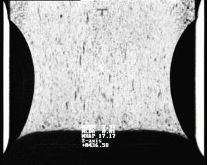
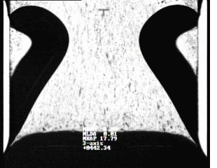
The filling of the compensation tube and the test section in the beginning of the experiment was accomplished within 25 seconds. The flow rate was increased in coarse steps from 3.0 to 8.5 ml/s without gas ingestion. The fine approach until the collapse of the free surface at 8.9 ml/s was achieved using steps of 0.05 ml/s. The flow was stabilized again at 8.0 ml/s to measure the velocity profile using the onboard LDV. Finally the length of the test channel was changed from 12 mm to 17.8 mm in fine steps of 0.4 mm. A second collapse could be observed at the end of the mission. The two pictures show a stable, steady flow with 8 ml/s at l = 17.7 mm and an unstable, unsteady flow with a slightly larger channel length.
The results will be used to corroborate our steady and unsteady one-dimensional flow models as well as our computations with FLOW-3D. Furthermore, aerospace engineers may use the results for the design of liquid acquisition devices in spacecrafts.
