Phase Separation in Capillary Channel
Motivation
Capillary channels are used in surface tension tanks to position and transport the propellant. If the liquid is exposed to the capillary channel, the capillary forces acts on it and the liquid runs through the channel to the tank outlet. This passive method for the transport of the propellant is functional all the time and requires no external power to operate as compared to active methods. However, the stability of the free surface in capillary channels is affected by the variable acceleration, vibrational disturbances and at high liquid flow rate as observed during the “Capillary channel flow” (CCF) experiment on-board the International Space Station. In low-gravity conditions, capillary pressure only balances the pressure difference across the liquid-gas interface. The gas ingestion into the channels due to unstable free surface degrades the quality of the propellant and severely affects the engine efficiency.
Objective
In propellant management devices (PMD), porous media are widely used for the phase separation process and delivery of vapor free propellant. In this project work, a capillary channel with an integrated porous medium is used to perform liquid gas phase separation in microgravity as well as under gravity conditions. The main objectives of the projects are:
- to demonstrate the ability of the device to separate phases in an environment with variable accelerations and
- to gather quantitative data on the ability of porous media to provide gas free supply of liquid.
A test facility is developed to validate the theory for an experimental campaign of 24 drop tower and 50 ground experiments.
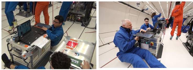
Based on the first experimental campaign, a second test facility is developed for the 33rd DLR parabolic flight campaign with Novespace in Bordeaux, France. During the 3 days campaign, 90 experiments are performed (30 each day) in microgravity and hyper gravity (1.8 g) condition.
Theory
A saturated porous media acts as a permeable medium to the liquid flow but blocks the gas unless the pressure difference across the porous media exceeds the bubble point pressure. The bubble point pressure depends on the characteristics of the porous media and type of the liquid. A Dutch twilled woven screen of type DTW 200x1400 is chosen as a porous medium because to its light weight and structural integrity. The choice of the test liquid is 3M HFE 7500, which has characteristics similar to storable propellants.
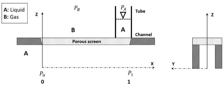
The test section consists of a rectangular plexiglas channel covered with a porous screen through which component A (liquid) flows (Figure 1). In the capillary tube on the outer side of the porous medium, component A exists. The pressure above the porous medium is PB in the gas phase, and PA in the liquid phase. The pressure at the inlet of the channel is P0. At zero mass flow rate, P0 = PA = PB, the system is in equilibrium and no mass transport takes place. If the mass flow rate is increased in positive x-direction, the pressure decreases along the length of the channel and component A enters into the flow channel from the capillary tube. The entering quantity depends on the pressure ratios and the cross-flow resistance of the porous medium. The porous medium saturated with component A blocks the gas breakage (component B) until the pressure across the porous screen exceeds the bubble point pressure.

Description of the Experiment
In the test facility, a low-pressure vessel regulates the inlet pressure P0. The liquid height in the capillary tube is raised by applying a suction pressure. A liquid flow rate is establish by a fluid pump. During the experiment, the top section of the capillary tube is exposed to ambient pressure by opening a valve. Due to the pressure difference, liquid from the tube enters into the channel through the porous screen. The saturated part of the porous screen on the upstream side blocks the gas breakage. The rate of liquid withdrawal into the channel from the tube can be regulated by lowering the inlet pressure P0 or by increasing the flow rate.

Contact
Publications
1) M. Conrath and M. E. Dreyer, Gas breakthrough at a porous screen, Int. J. Multiphas. Flow, 42 (2012), pp. 29–41
2) P. J. Canfield, P. M. Bronowicki, Y. Chen, L. Kiewidt, A. Grah, J. Klatte, R. Jenson, W. Blackmore, M. M. Weislogel and M. E. Dreyer, The Capillary channel flow experiments on the International Space Station: Experiment set-up and first results, Exp. Fluids, 54 (2013), pp. 1–14.
3) P. Bronowicki, P. Canfield, A. Grah and M. E. Dreyer, Free surfaces in open capillary channels - Parallel plates, Phys. Fluids, 27 (2015), pp. 1–21.
Acknowledgement
The project under the grant number 50WM1745 is funded by the German Aerospace Center (DLR).


 "
"