TEXUS Experiment
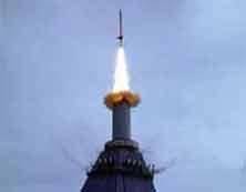
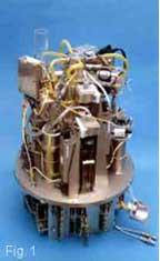
The experiment was performed during the campaign TEXUS-37 (Technologische Experimente unter Schwerelosigkeit) during a suborbital flight. The rocket was launched from the Swedish launch site Esrange on March 27th, 2000 at 13:17 local time. The ballistic flight reached an apogee of approximately 243 km exposing the payload to microgravity (< 0.0001 g) over a period of five minutes and 49 seconds. Lift-offmass was 369,2 kg excluding the 2-stage rocket engine Skylark 7. During the microgravity period the experiment module (Fig. 1) was manually driven via telecscience.
Experimental set-up
A schematic of the experimental setup is shown in Fig. 3. The core element of the setup consists of a cylindrical liquid reservoir (2) with a compensation tube (7) and an observation chamber (1) with the open channel. The channel is connected to the liquid reservoir (2) via a nozzle (3). The compensation tube as well as the nozzle can be closed pneumatically by a gate valve (8) and a stemple (4). The liquid reservoir was especially designed to enable a controlled filling of the channel at the beginning of the microgravity phase and provides defined boundary conditions at the channel inlet. The flow through the channel is established by two gear pumps. One pump Pu1 supplies thereservoir through a circular gap on the bottom of the reservoir atflow rate Q1. The flow enters through a screen-controlled rectifier (5) to ensure a homogenous velocity distribution. The second pump (Pu2) withdraws the liquid via
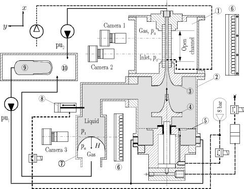
via the channel and the nozzle from the reservoir at flow rate Q. The unavoidable flow rate differences between both pumps are accommodated by the perspex compensation tube (7) (inner diameter 45 mm).
The capillary channel consists of two parallel quartz plates with breadth b = 25 mm, gap a = 5 mm and length l = 46.6 mm. A front view normal to the plates is shown in Fig. 4(a). The channel has precise markings for the calibration and evaluation of the video images. Two CCD cameras were used. The camera fields of view overlapp by approximately 10 mm, and the image resolution is 47 mm/pixel. A homogenous illumination is achieved by an LED panel with a Teflon diffusor (6). Due to total reflection the profiles of the gas-liquid
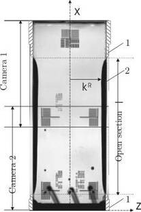
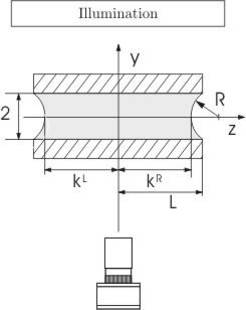
interfaces appear as dark zones on the video images. Referring to Fig. 4(b) they are defined by the distances L-k, where the positions correspond to the left and right hand side profiles of the surface shape in the plane y = 0, respectively. During the experiment the video signals were downlinked to the ground and recorded on VCR (S-VHS quality).
